Main Engine Room
Overview:
Welcome to the Main Engine Engine room of an LST. This compartment is located on the fourth deck, between the auxiliary engine room and the shaft alleys. It is only accessible by two vertical ladders. One enters the compartment via vertical trunks. One is located on the port side and the other on the starboard. These ladders can be accessed from the port or starboard wing deck or from hatches on the main deck. Here two 12-567A engines from the Electro-Motive Division of General Motors Corp drive the LST. When the ships were built, that division of GM was producing the engine for use in railroad locomotives. This decision greatly reduced the time required to design and test a suitable means of power. Although the power plant selected was not extremely powerful, it was capable of driving the LST at slightly over 10 knots, and was proven to be reliable in operation. The twin-engine, twin-screws were directed by the engine order telegraph which provided for Stop, and speeds of One-Third, Two-Thirds, Standard, Full, and Flank (ahead and back). Early LST’s engine order telegraph markings were One-Third, Two-Thirds and Full (in back mode).
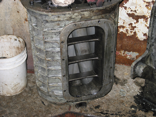
 This is a view up the trunk that one must ascend or
descend into the engine room. There are six trunks total; 2 to the main engine
room, 2 to the auxiliary engine room and two to the shaft alleys. (click
for larger picture)
This is a view up the trunk that one must ascend or
descend into the engine room. There are six trunks total; 2 to the main engine
room, 2 to the auxiliary engine room and two to the shaft alleys. (click
for larger picture)
Engine Specifications:
Unit Designation: #12-567A
Manufacturer: Electro-Motive Division of General Motors
Horsepower: 900 Brake Horsepower (shaft)
Design: V-12 with 45° angle between banks, 2 cycle, 6,810 cubic inches displacement
Bore & Stroke: 8-1/2" x 10"
Compression Ratio: 16 to 1
Rotation: Counter-clockwise when viewed from air clutch end
Cylinder Numbering: Rightside 1 to 6; Leftside 7-12 when viewed from rear of engine
Firing Order Port Engine: 1,6,8,11,2,5,9,10,3,4,7,12 with clockwise crankshaft rotation and clockwise rotation at line shaft (aft Falk GBox)
Firing Order Starboard Engine: 1,12,7,4,3,10,9,5,2,11,8,6 with counter-clockwise crankshaft rotation and clockwise rotation at line shaft
(aft Falk GBox)
RPM Range: 275 RPM - idle, 744 RPM full speed, 800 RPM flank speed
Engine operating temperature: 165°F (do not exceed 180°F)
Crankshaft journal: 7-1/2” diameter
Crankpin journal: 7-1/2” diameter
Compression rings: 3
Oil control rings 2
Lubricating oil pressure: 28# @ 744 rpm (20# at 275 rpm) (40# cold)
Piston cooling oil pressure: 20-30# @ 744 rpm (8# at idle)(Piston cooling oil was injected into the funnel on the piston to cool the piston and
lubricate the wrist pin)
Lubricating oil temperatures: 140°F minimum; 180°F maximum
Fresh water temperatures: 140°F minimum; 170°F maximum
Outlet salt water temperature: 130°F MAX (higher = salt deposits)
Auxiliary generator output: constant 76 volts
Battery: 32-cells, rated @ 426 Amp-Hrs (8 hr rating) Gravity 1230-1250
Solid unit injector in each cylinder head
Two blowers supply fresh air at 3# to 5# pressure (above atmospheric) to the space around the cylinders at a temperature not to exceed 140°F to provide scavenging air to the engine
4 exhaust valves per cylinder
Fuel pump motor rated @ 1/4 HP @ 1,150 RPM
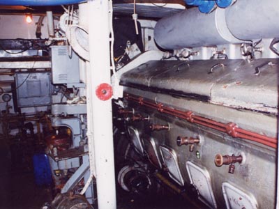
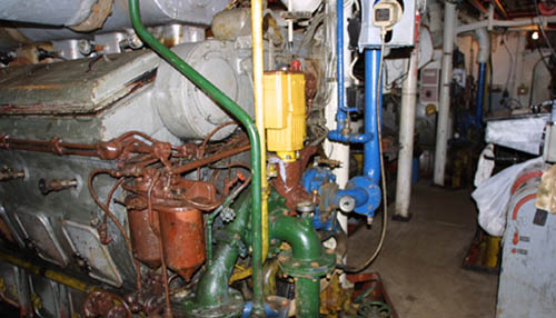
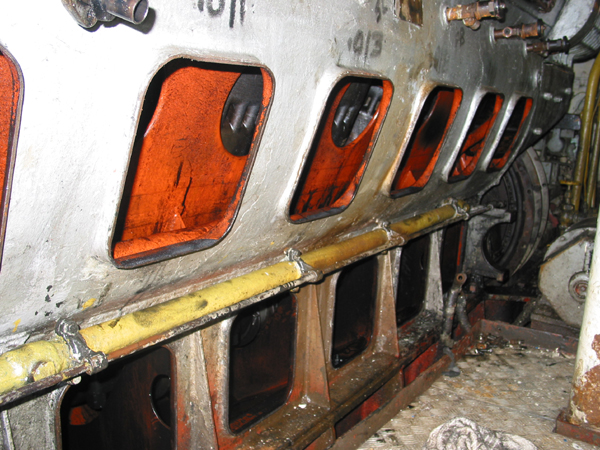
Engines:
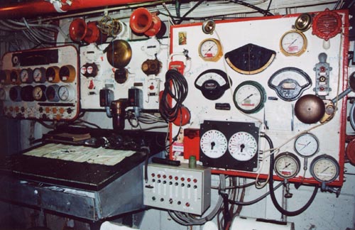
Multiple views of the 12-567A's aboard the LST 325. The last picture shows main engine room instruments. (click to see larger picture)
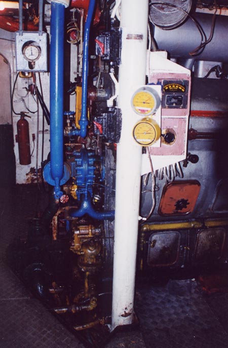
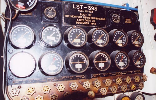
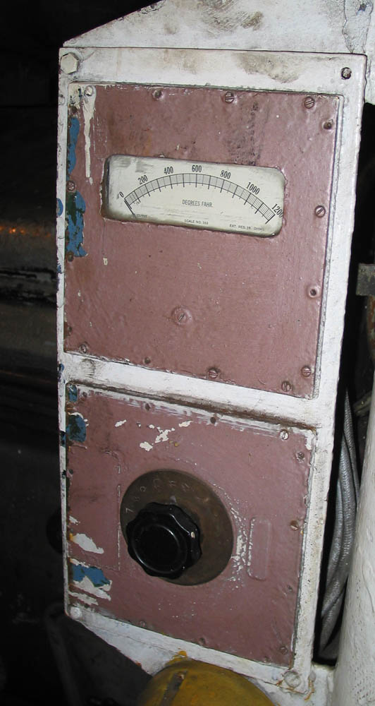 This gauge is a pyrometer, it indicates exhaust temperature in selected
cylinder. The cylinder is selected by the rotary switch below.
This gauge is a pyrometer, it indicates exhaust temperature in selected
cylinder. The cylinder is selected by the rotary switch below.
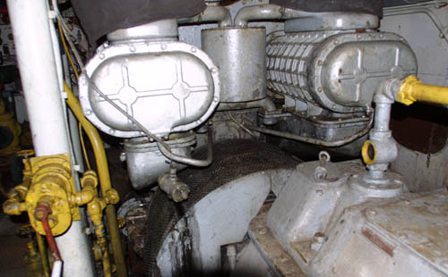
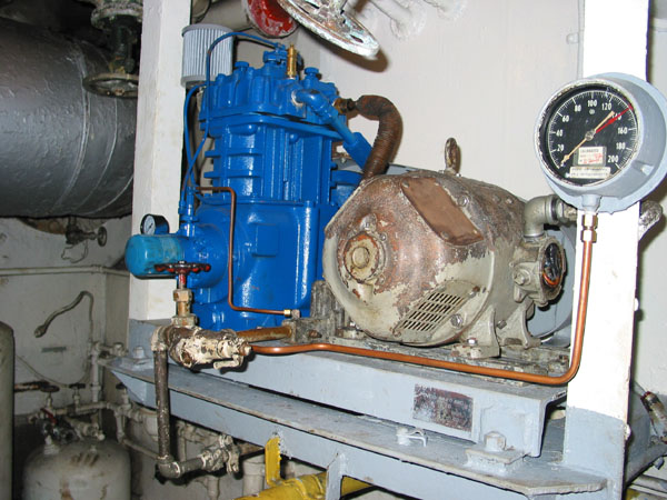 One of the two compressors that supplies air the the air clutches.
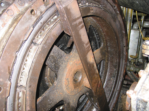
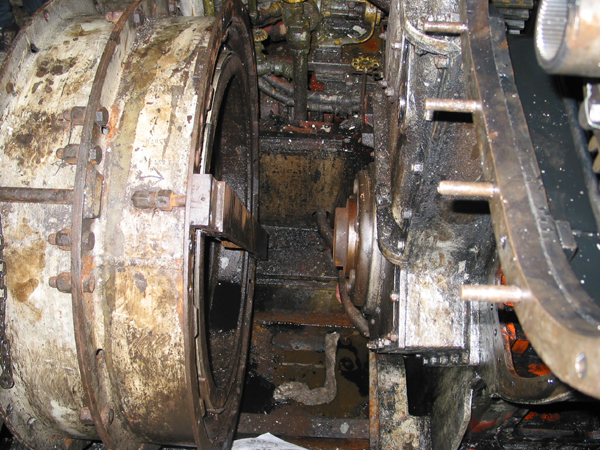 Pictures taken during servicing of 12-567's aboard LST 325.
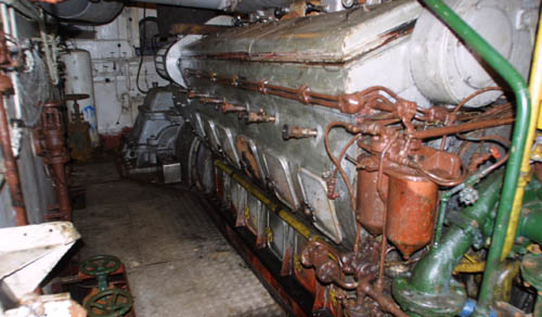
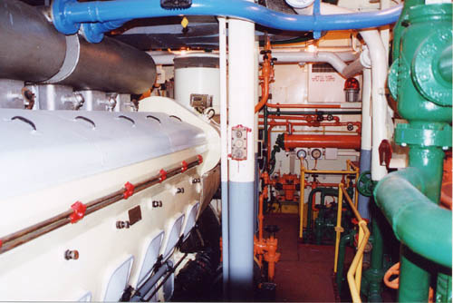
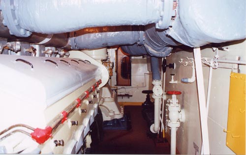
Two views of the 12-567A's aboard the LST 393. The third picture shows a close-up of some of the instruments in the LST 393's engine room. (click to see larger picture)
Click below for more details about the Main Engine Room.