AUXILIARY ENGINE ROOM
Welcome to the auxiliary engine room of an LST. This compartment is located on the fourth deck, forward of the main engine room. It is only accessible by two vertical ladders. One enters the compartment on the port side and the other from the starboard. These ladders can be accessed from the port or starboard wing deck or from hatches on the main deck. In this compartment electricity is produced to run all of the electrical equipment aboard the ship. As you step out of the access trunk you will immediately see the three auxiliary engines and the switchboard behind the engines. On the forward bulkhead are a series of valves, which control the ballast tanks aboard the ship. Beneath your feet are steel plates that can be removed in order to access the bilge. The bilge is the area between the lowest deck in the ship and the ship's bottom. Here many pipes run fuel, fresh water and ballast water all over the ship.
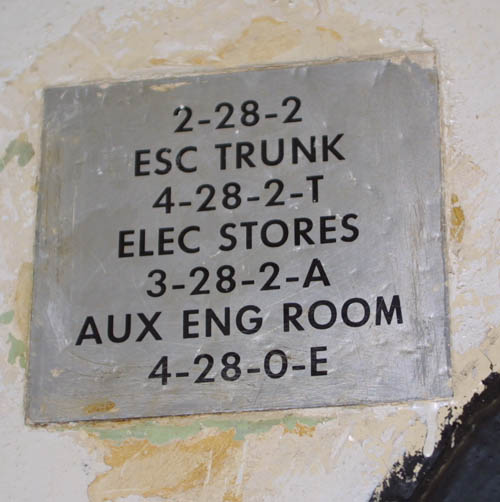
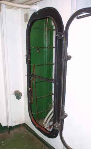
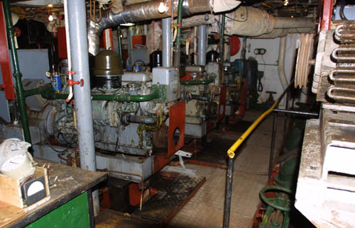
First, shows the label at the upper end of trunk leading to Auxiliary Engine Room (explanation of labels). Second, the hatch itself. Third the view of the auxiliary engine room from the bottom of the trunk.
LST's were produced with a variety of auxiliary engines. These included the Detroit Diesel Inline 6, the GM three cylinder and the Superior GDB-8. The LST 325 is equipped with the Detroit Diesel Inline 6, while the LST 393 is equipped with the Superior GDB-8. Each engine, regardless of type, is connected to a generator, which produces an output voltage of 240/120 VDC. Where AC current is required, the DC current is converted through use of a Motor-Generator set. Under normal steaming conditions, only 1 auxiliary engine was kept running. This one engine and its generator were enough to provide electricity to the lights and other necessary accessories the crew might need during a normal day. During beaching or when at general quarters all three auxiliary engines were brought online. During conditions such as these the ships demand for electricity would increase dramatically. Tank deck blower fans, the stern anchor winch, bow door and ramp machinery, ballast pumps and numerous other systems could place a heavy demand on the auxiliary engine room.
Specifications:
| Manufacturer | GM-Detroit Diesel | GM-Detroit Diesel | GM | Superior |
| Model # | 3-71 | 6-71 | 3-268-A | GDB-8 |
| Cylinders | 3 | 6 | 3 | 8 |
| Bore | 4-1/4" | 4-1/4" | 5-1/2" | |
| Stroke | 5" | 5" | 7" | 7" |
| Displacement | 212.7 | 425.3 | NA | NA |
| HP @ max 2000 RPM | 83 | 165 | NA | NA |
| HP 1200 RPM | 63 | 125 | NA | NA |
| Max Torque @ 1000 RPM | 262 ft. lbs. | 525 ft. lbs. | NA | NA |
| Firing order (RH drive) | 1-3-2 | 1-5-3-6-2-4 | NA | NA |
| Firing Order (LH drive) | 1-2-3 | 1-4-2-6-3-5 | NA | NA |
| Dry Weight | 1186 lbs. | 1597 lbs. | NA | NA |
| Lube Oil Quarts | 16 | 34 | NA | NA |
| Water Capacity | 9.5 gal | 21.5 gal | NA | NA |
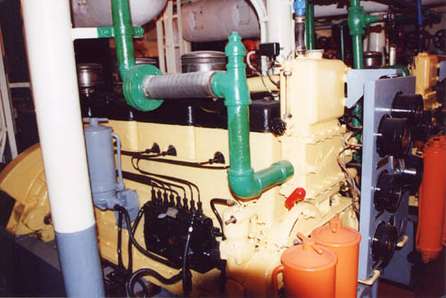
Engines:
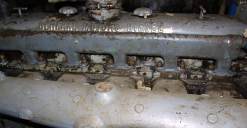
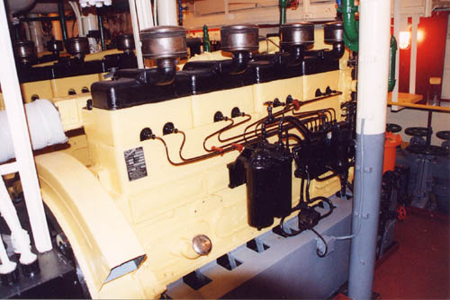
Two views of one of the Detroit Diesel Inline 6's aboard the LST 325. The third shows the GM name on the engine. (Click to see larger picture)
Movies!!
Click here for movies of auxiliary engine room.
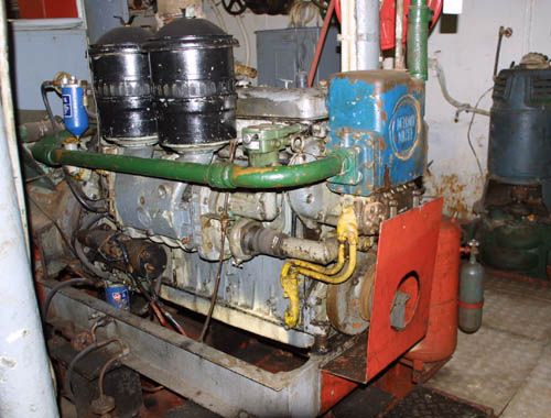
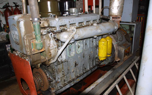
Two views of one of the Superior GDB-8's aboard the LST 393. (Click to see larger picture)
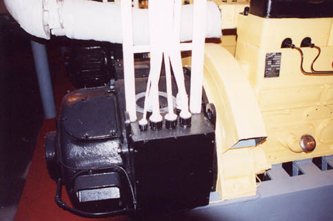
The left picture shows a generator on the aft end of a GDB-8. (Click to see larger picture)
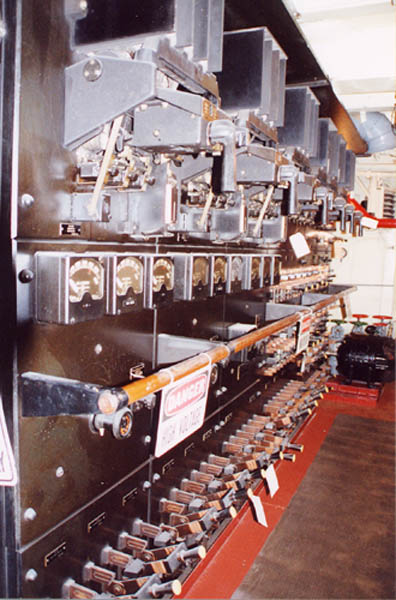
Switchboard:
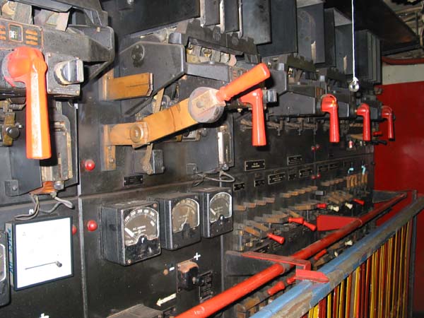
The distribution of electricity is controlled through a series of six (6) power panels mounted with circuit breakers and switches comprising the switchboard. These panels run from left to right when facing the the switchboard. Below is the switchboard in the auxiliary engine room of LST 393. (Click to see larger picture)
Panel #1 -- D.C. Generator #1 & Power Feeders: This panel receives power from 100-KW D.C. Generator #1, through a 500-Ampere D.C., 3-Pole, 3-Coil, type “KB” A.C.B. Circuit Breaker equipped with reverse current trip and “Hold- In” device. Mounted on this panel are instruments, and instrument switch, and generator field rheostat and three (3) power feeder circuits. D.C. ammeters with their shunt indicate the current in the positive and negative generator cables. Facing the front of the switchboard, the ammeter on the right indicates current in the positive cable, and the one on the left indicates the current in the negative cable. The voltmeter may be used to indicate either generator or bus voltage. By turning the eight-stage voltmeter switch to positions #1, #2, or #3 the generator voltage is indicated. In positions #4, #5 and #6 the appropriate bus voltage is indicated.
Panel #2 -- D.C. Generator #2 & Power Feeders: This panel receives power from 100-KW D.C. Generator #2, through a 500-Ampere D.C., 3-Pole, 3-Coil, type “KB” A.C.B. Circuit Breaker equipped with reverse current trip and “Hold- In” device. Mounted on this panel are instruments, and instrument switch, and generator field rheostat and three (3) power feeder circuits. D.C. ammeters and voltmeter on this panel operate exactly the same as on the Panel #1.
Panel #3 -- D.C. Generator #3 & Power Feeders: This panel receives power from 100-KW D.C. Generator #3, through a 500-Ampere D.C., 3-Pole, 3-Coil, type “KB” A.C.B. Circuit Breaker equipped with reverse current trip and “Hold- In” device. Mounted on this panel are instruments, and instrument switch, and generator field rheostat and three (3) power feeder circuits. In addition to the ammeters and voltmeter on Panel #1, and #2, this Panel contains an ammeter with zero-center scale to indicate current in the neutral ground connection. The voltmeter is a twelve-stage switch, and positions #1, #2, or #3 indicate generator voltage. Positions #4, #5, or #6 indicate bus voltage. Positions #7, #8 or #9 indicate shore power voltage.
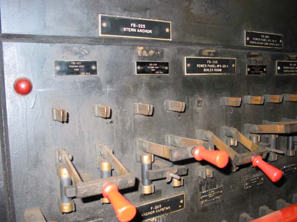
Panel #4 -- D.C. Power Feeders: This panel receives power from the generator bus and may be fed from either generator running separately or any combination of generators operating in parallel. On the top section are mounted two (2) type “KB” A.C.B. Circuit Breakers. One of these is a 400-Ampere D.C., 2- Pole, 2-Coil, manually operated for the stern capstan feeder. The other breaker is a 350-Ampere D.C., 2-Pole, 2-Coil, manually operated for the ventilating tank space feeder. On the lower section are mounted fourteen (14) fused knife switches for 2-wire feeder circuits. Ten (10) for active circuits and four (4) spares.
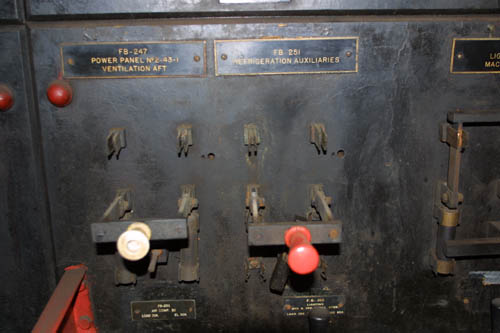
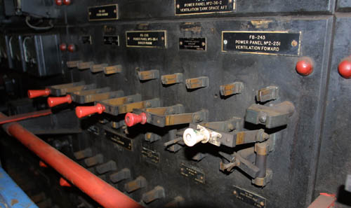
 Close-up
pictures of the Panels aboard LST 325.
Close-up
pictures of the Panels aboard LST 325.
Panel #5 -- Shore Power, Lighting Feeders,
Power Feeders and Battery Charging Circuits: This panel receives power from
the generator bus. Located on the top section is the Shore Connection Breaker
of 400-Amperes, 3-Pole, 2-Coil, manually operated. Also on the top panel is
the Shore Power Indicating Lamp, and the charging ammeter, with knife switches
for various battery charging circuits. On the lower section are mounted
sixteen (16) fused knife switches for feeder circuits. Eleven (11) are active
3-wire circuits, two (2) for active 2-wire circuits, and three (3) for spare
2-wire circuits.
|
Panel#6 -- Power Feeder Circuits: This panel receives power from the generator bus. Mounted on the panel are three (3) fused knife switches, one for an active 2-wire circuit, and two (2) for spare 2-wire circuits.
Other Equipment:
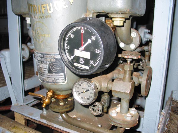
Diesel Purifier
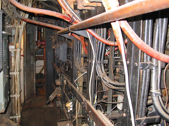
View behind the main board