Design and Construction
The
Design:
On
4 November 1941, John C. Neidermair, a designer with the Bureau of Ships,
submitted his first drawing of the LST. Mr.
Neidermair had a long and illustrious career with the Bureau of Ships, having a
part in the design of over 8,000 ships. It
was to be 280 feet long and 45.4 feet wide.
After consideration and calculations for buoyancy, stability, and payload
requirements, the final drawings resulted in a 328-foot length, a 50-foot beam,
a flat-bottom, a sloping keel, giving a 7-1/2-foot maximum draft (forward), and
a 14-foot maximum draft (aft), with about a 16-foot freeboard. The tank deck dimensions were 230-feet long, 30-feet wide,
and 12-feet high. John Neidermair
insisted upon 3/8” plating for the hull (shell plating), rather than the
planned original 1/4”, and the plating under the bow was 1” thick.
The firm of Gibbs and Cox, New York, completed the actual design details,
and became the contractor charged with the procurement of materials/equipment,
and they selected the Dravo Corporation as the first contractor.
John C. Neidermair insisted the design should contain no more shapes and sizes of plates than you have fingers on your hand -- five of each. The LST required 30,000 parts, including such items as steering gear, stern anchor gear, armament, snaking winch, appliances, refrigeration plant, ladders, doors, pumps, engines, stanchions, main generator and power distribution switching gear.
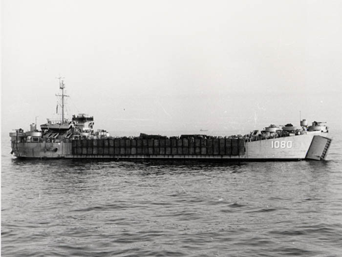 LST 1080 with pontoons circa 1955 (photo by Morris
Smith)
LST 1080 with pontoons circa 1955 (photo by Morris
Smith)
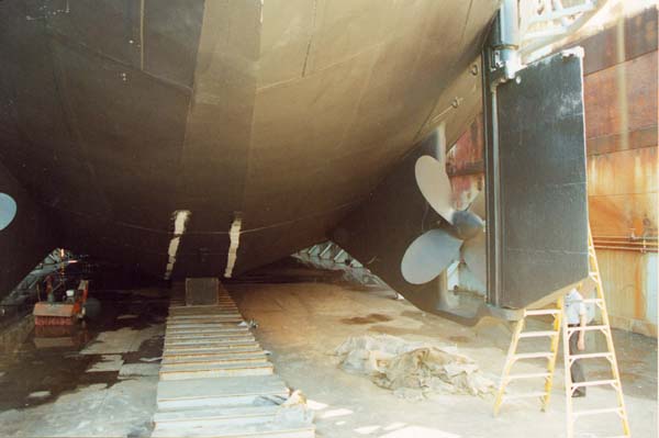
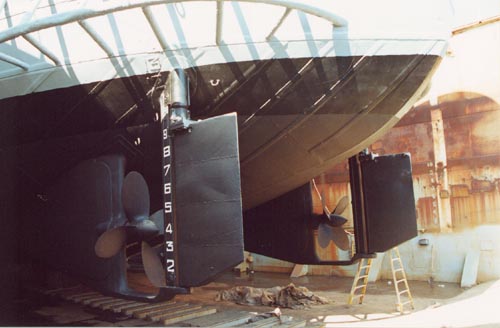
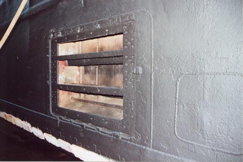
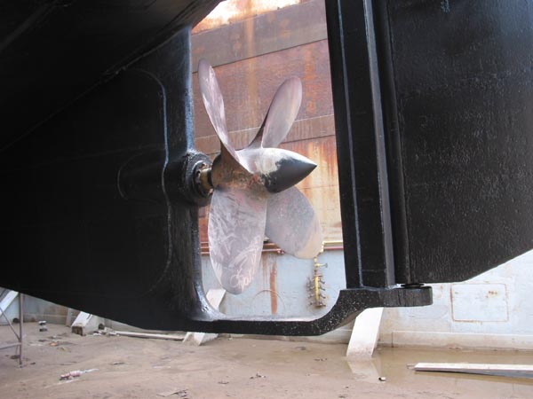
The LST was designed to ground evenly (from bow to stern) on a beach with a slope of about one-foot for every fifty-feet (the design gradient). Each propeller (screw) is protected by a skeg which extends forward from it and provides a sturdy “runner” beneath its blades. The twin rudders are mounted directly behind the screws, and thus achieve maximum effectiveness as a result of the propeller discharge. The propellers were spaced almost 40-feet apart and set up clear of the base line of the hull. The sea chests, or intakes for sea water, were located on the sides of the hull.
 (click for larger picture)

The
LSTs actually took more man-hours to build than the Liberty and Victory (cargo)
ships, which were almost 5 times larger; about 10,600 tons deadweight to the
LST’s 2,180 tons. Some
compromises in construction difficulty/cost/time constraints were made.
Using a flat-plate design to form the turn at the bilge would have added
16-25% more water resistance, and adversely affected the 10-knot speed desired.
The decision was a curved bilge. Constructing
a curved (cambered) main deck would have drained water more readily, but added
to the construction time and cost. The decision was to build a flat main deck.
The first LSTs were
designed with an elevator to carry equipment between the tank deck and the main
deck.
This was a time-consuming process which the “LST-511 class” improved
upon by replacing the elevator with a ramp that was hinged at the main deck for
this purpose.
It permitted vehicles to be driven from the main deck to the leading edge
of the tank deck, across the bow ramp to the beach or causeway. Some
other modifications, with the “LST-542 class”, included the installation of
the (Conn) navigation bridge [3rd level above the main deck] atop the
Captain’s sea cabin, the installation of a water distillation plant with a
capacity of 4,000 gallons per day, removal of the tank deck ventilator tubes
from the center section of the main deck, strengthening the main deck to carry
an LCT (Landing Craft, Tank), and an upgrade in armor/armament. These modifications were not major structural changes, and
1,055 LSTs were built on this “platform” before the next class--USS
Terrebonne Parish (LST-1156) was launched in August 1952.
The ship could carry 1,060 tons of diesel fuel in ballast tanks. Draft forward could be as little as 1-1/2-feet when unloaded and unballasted. The LSTs were actually loaded for ocean passage to as much as 1,600 tons on the tank deck, and 300 tons on the main deck, and resulted in 33.3 tons per inch of immersion. The draft forward with a 1,900-ton payload was about 8-feet. For beaching, the designed load was 500 tons, and the actual load was an average of 700 tons.
The
design was excellent in many ways. The
hull was double-bottomed, and water-tight compartments lined the entire sides of
the ship, offering some protection to the engine room spaces.
The double-bottom compartments contained salt-water, diesel fuel, and
fresh water, in a grouped arrangement order progressing from the bow to the
stern.
Construction:
Production
of the “LST-1 Class” was begun late in l942 and continued through 1943.
The “LST-511 Class” was built in 1944, with the “LST-542 Class”
being built in 1944 and l945.
Production
costs averaged $1.6 million per ship for the LST-542 class, versus $1.4 million
for the LST-1 and LST-511 classes.
Brief Statistics:
| Hull | All-welded steel 3/8” thick |
| Length | 327’ 9” |
| Beam |
50-feet |
| Displacement empty / full | 1,650 / 3640 (LST 1) 4080 (LST 511) |
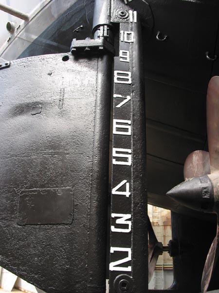
| Design draft forward / aft | 6’ 8-1/2” 13’ 0-3/8” [Displacement @ D.D. 3,590 tons] |
|
Empty draft forward / aft |
1'6" / 10'6" |
| Full load draft forward / aft | 8' / 14'6" |
| Beaching trim forward / aft | 3' to 6' / 10' to 13' |
| Freeboard | 16'6" |
| Engines | 2 (GM V-12 Diesel - 12-567A) |
| Screws | 2 |
| screw horsepower | 1,700 |
Builders:
American Bridge, Ambridge, PA- LST 137-141, 261-295, 653-681, 754-771, 829-849, 1081-1095
Bethlehem-Fairfield Co. Baltimore, MD- LST 401-430
Bethlehem-Hingham, Hingham, Mass- LST 906-979, 1060-1080
Bethlehem Steel, Quincy, MA- LST 361-382, 1004-1027
Boston Navy Yard -LST 301-310, 980-1003, 1028-1037
Charleston Navy Yard, Charleston, SC -LST 353-360
Chicago Bridge & Iron, Seneca, IL -LST 132-136, 197-231, 511-522, 600-652, 772-774, 850-860, 1115-1152
Dravo Corp., Pittsburgh, PA - LST 1-5, 7-15,17-20, 22-24, 26-60, 730-753, 775-796, 884-905, 1038-1059
Dravo Corp., Wilmington, DE -LST 6, 16, 21, 25
Jeffersonville Boat, Jeffersonville, IN -LST 61-84, 117-121, 181, 501-510, 523-530, 682-729,797-805, 861-873, 1096-1100
Kaiser, Inc. Vancouver, WA -LST 446-475
Kaiser, Inc. Richmond, CA -LST 476-490
Missouri Valley Bridge & Iron, Evansville, IN -LST 122-131, 157-180, 237-247, 491-500, 531-599, 806-828, 874-883, 1101-1114
Newport News Shipyard, Newport News, VA -LST 383-400
Norfolk Navy Yard, Norfolk, VA -LST 333-352
Philadelphia Navy Yard, Philadelphia, PA -LST 319-332